The different methods of aircraft structural repair procedures
The importance of knowing the different methods of
aircraft structural repair procedures is readily apparent given today’s tight
fiscal environment. As a maintenance officer, you will be expected to
understand many areas of aircraft structural repair. This lesson concentrates
on the different types of aerospace materials used on today’s aircraft and
their application.
Key Points:
Structural materials;
Non-ferrous metals;
Filamentary composite materials;
Advanced composites;
Advanced composite repair
techniques;
Additional aerospace materials;
Techniques for aircraft
structural fabrication and repair;
Temporary structural repair
requirements.
Click here for the previous lessons, to learn about: Principle of Airframe; Principles of Aerodynamics; Airfoil Characteristics; Primary Flight Control Surfaces; Description and Operation of Helicopter; Miscellaneous Components of an Aircraft…
Structural
Materials
METALS.
The metals that are used in the make up of an aircraft
must be strong and be able to withstand the stress related with flight. The
density of metal is the weight of the metal per volume, measured in pounds per
square inch. Strength is the maximum stress that a material can withstand
before failure. Here is a basic list of the type of stress or forces that can
affect aircraft surfaces:
• Tensile strength is pulling force occurs.
• Compressive strength is pushing force.
• Strain is referred to as the strain of any force
over the length of the surface. • Modulus elasticity is referring to the
stiffness of the material.
Ferrous.
Ferrous metals
are those containing iron as the main metal. Iron, itself is heavy, relatively
soft, and not used on aircraft. However, steel is an alloyed metal that
contains iron, carbon and other non-ferrous metals. Steel, especially stainless
steel, is very useful in certain airframe applications. Steel alloys take on
the conductive and magnetic characteristics of a ferrous metal.
Steel.
Steel is rated by its carbon content:
• Low carbon steel (0.1-0.3%) is seldom used except as
secondary structural parts and clamps.
• Medium carbon steel (0.3-0.5%) has high strength and
is used in landing gear and flight control components.
• High carbon steel (0.5-2.0%) is hard and brittle,
rarely used on aircraft, mostly used on coil springs.
Stainless steel is a special class of steel,
containing chromium and nickel, and is used in high temperature applications.
It can be found in exhaust systems and the hydraulic lines of many aircraft.
Stainless steel has a high strength to weight ratio and resists corrosion and
heat as well.
Non-Ferrous
Metals
Aluminum.
Aluminum is a light; but strong metal used extensively
in structural members and aircraft skin (especially in older aircraft).
Aluminum is malleable and relatively easy to work with. Different types of
aluminum have been given industry-wide designations by their alloy type. Common
alloy-types:
• 2024 – used on many aircraft for secondary structure
and skin. • 7075 – found in areas that high strength is required.
Titanium.
Titanium is 43% lighter than stainless steel but
stronger. The most popular type of alloy used in the aerospace industry is
6AL-4V (meaning that the titanium is alloyed with 6% aluminum and 4% vanadium).
Titanium is very corrosion resistant and is unattached by most acids, by moist
chlorine gas, or by common salt solutions. Titanium resists heat extremely well
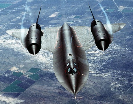
and is therefore used in many high speed aircraft as shown in figure 1-49. It
is also expensive, and replacements for titanium are being researched. New
alloys for titanium, even composites mixed with titanium (or titanium-matrix’s)
are being researched and tested, particularly for use as replacements for steel
landing gear actuators and struts.
Magnesium.
Magnesium is the lightest structural metal. It is very
brittle, porous and seldom used in its pure state. Used widely by aircraft
builders in the past, magnesium is being phased out of military aircraft for
three reasons: 1. It corrodes easily
2. It is difficult to work with
3. It is highly flammable
Other non-ferrous metals include to clad pr plate
parts to protect them from corrosion. Cadmium is commonly used for many parts,
though it has a bad reaction with titanium. Nickel, Zinc, and even Aluminum are
used to protect parts as well.
NON-METALS.
Nonmetals used in aircraft construction vary widely in
type, composition, and application. The earliest aircraft were built with wood
and cloth, with some metal parts. New aircraft are being made of advances
composite materials, ranging from graphite to experimental uses of
titanium/composite matrix to replace steel components.
Plastics/Acrylics.
Used for
decades in aircraft, plastics offer many advantages over wood and metal
structures. Plastics are light, have good strength, and may be used in many
non-load bearing areas. Canopies, consoles, and other aircraft parts are frequently
made of plastic. There are many different plastics in use today including synthetic
resins (such as acrylic, nylon, and vinyl), cellulose plastics (used on older aircraft),
thermosetting plastics (those which retain their shape after manufacturing and are
not re-formable, such as polyester), and thermoplastics (plastics which may be reheated
and reformed).
Phenolic.
Phenolic is a special type of plastic; it is actually
a combination of plastic and wood or paper. When wood based material is set in
plastic, it becomes harder and stiffer then plastic alone, but does not have
the strength or heat resistance necessary to be used in a primary structure.
Phenolics are found in computers (as circuit boards), flight control rigging
(pulleys), hydraulics (as clamps to hold lines in place), and many other areas.
The advantage of a Phenolic clamp for a hydraulic line over steel on is the
pheniloc one will not chaff (scratch) the steel line. The Phenolic clamp will
take the damage induced by aircraft vibrations, but will save the hydraulic
line from being damaged.
Filamentary
Composite Materials
A material consisting of two or more physically different
solid constituents, each of which largely retains its original structure and
identity. Composites are distinct from alloys in that their structure is
engineered by mixing two materials in an intimate solid mixture, with one
component being embedded in the other, usually an adhesive or epoxy type of
material and a fibrous type of material. A common feature of composite materials
is the use of small quantities of a relatively expensive, strong, often fibrous
material to reinforce the bulk of a cheap matrix material. The properties of
the resulting composite are usually intermediate to those of the components
from which it is made. However, certain properties, notably toughness or
resistance to fracture, are much better than those of either of the components,
giving composites with unique properties. A simple example of a composite is
clue on a piece of fabric; it is stronger than either material by itself, but
now is a more solid surface type of material. Refer to Figure 1-50, 1-51 and
1-52.
Desired Characteristics of Matrix Resins
Mechanical
& Thermal Processing Characteristics
-High strength
-High elastic elongation
-High shear strength
-High modulus
-High heat distortion temp
-Low creep at use temp
-High toughness/impact strength -Thermal
expansion near fiber -Resistance to thermal degradation -Low thermal
conductivity
Chemical Properties:
Good bond to fiber (directly or
with coupling agent)
Resistance to solvents &
chemicals
-Low enough melt or solution
viscosity and surface tension to permit thorough fiber wet-out
-Good flow characteristics
-Rapid cure or solidification
-Suitable for pre-coated
reinforcement
-Cure temp. not greatly above use
temp
-Low shrinkage during and after molding
-Long shelf life and pot life
Other Factors:
Low cost
Low density
Low dielectric constant
Low moisture absorption
Comparison of Thermoset and
Thermoplastic Resins
Thermosets Thermoplastics
-Most used
-No flow under heat and pressure
after cure; scrap discarded
-Amorphous
-Applied to reinforcement as low
viscosity liquids or varnishes
-Phenolics and most polyimides
emit volatiles on curing
-Stepwise cure possible to permit
control of viscosity & handling
-Post curing often necessary for
optimum properties
-Higher strength, modulus and
average use temperature
-Used with continuous fiber and
discontinuous fiber (usually >1/4”) possible with some plastic yielding
-Used mostly with discontinuous
fiber (Length usually <1/2”), though much Activity in last 10 years on TP
prepregs
-Relatively high tensile
elongations -High variability in mechanical properties
-Most suited to automated
production
-Softening and/or melting points
remolding of scrap usually possible
-May be crystalline
-High viscosity even in the melt;
reinforced by dry or melt compounding
-No volatiles emitted during
molding
-Viscosity varied only by
increase in temperature and/or shear rate
-Post molding shrinkage may be
severe due to slow crystallization
-Tougher, less brittle and lower
cost -Low tensile elongations
-Variability in mechanical
properties
Figure 1-50, Figure
1-51, Tensile Strength of Composites Elasticity of Composites
Figure 1-52, Strength of Composites
ADVANCED
COMPOSITES
Composites referred to by type of fiber/type of
matrix, layers can be fiber only for later “wet” lay-up (adding resin), or can
be “prepreg” (already containing the resin)
Tape - all
fibers aligned in single direction
Cloth - fibers aligned in multiple (usually two)
directions
Plain weave: over and under one fiber at a time
Satin weave: over several then under one fiber
Graphite/Epoxy.
Graphite epoxy is produced by subjecting strands of
synthetic materials (graphite) to intense heat and pressure, after which the
filaments (containing 3,000 to 16,000 strands each) are organized into
unidirectional tapes or woven into fabrics. Graphite epoxy materials are
extremely stiff, have high tensile strength, and low density. Components made
of graphite epoxy are lighter than aluminum, or woven fiberglass, but strong
enough to be used as primary structures (and frequently as flight control
surfaces or weapons bay/landing gear doors due to their low radar signature). Many
newer aircraft are using a substantial amount of graphite epoxy in their
primary structures; resulting in lighter, more fuel efficient aircraft.
Aramid/Epoxy (Kevlar).
Aramid epoxies
are a lightweight polymer material with exceptional tensile strength. They are
usually yellow-gold in color. Aramids were developed in 1965 during a research
project to design a strong and lightweight fiber.
Used in flight suits and hazardous-material handling
gear, Nomex is an example of an Aramid, the most common Aramid used in
aircraft, though, is known as Kevlar. Kevlar is 30-35% lighter than fiberglass,
but not stiff enough to be used in primary aircraft structure. A distinguishing
feature of Kevlar fibers is their low compression strengths, giving the
material good energy absorption characteristics. As a result, Kevlar is often used
to replace titanium or steel armor plating, being much lighter and having
better impact resistance than most metals. Examples of use included bulletproof
aircrew seats, high strength ropes, personal armor, helmet, rotor blade bullet
resistant coatings, flight control surfaces, and aircraft cowlings. Aramids are
repaired with methods similar to those used on fiberglass, though extra care
must be taken to limit ultraviolet (sunlight) and moisture penetration on
Aramid structures.
Boron/Epoxy.
Boron epoxy is formed by depositing boron trichloride
(as a vapor) onto 0.005-inch tungsten fiber. Boron fibers are stiffer, stronger,
harder, and lighter (one-fourth the weight of steel) than conventional metals.
In hardness, boron ranks second to only diamonds. Due to its high stiffness,
twice that of steel, boron cannot be formed onto a tight radius, that is, parts
made of boron are limited to flat surfaces (such as vertical/horizontal
stabilizers). Working with boron can be hazardous. The fibers are thin enough
and stiff enough to pass through a technician’s hand, or become airborne, if broken
off or inhaled. Boron composite materials are easily distinguished by their grayish-black
color.
Figure 1-53,
C-17 Composite Material
Newer materials.
Composite materials, as shown in figure 1-53, 1-54 and
1-55 such as carbon- fiber or glass-fiber reinforced plastics, are now widely
used, due to their superiority over metals, in applications requiring high
stiffness and strength as well as low weight. A major concern about the use of
composite laminates for structural applications is however their low-resistance
to out-of-plane localized impact loadings, likely to occur during manufacture,
service or maintenance. While metal structures may absorb impact energy by
plastic deformation, usually without any major effect on the load carrying
performance, energy dissipation in composite materials mainly occurs through a
combination of fracture modes such as matrix cracks, delaminating and fiber fracture,
which may cause significant reductions of residual strength and modify the structural
response of the component.
Glass epoxy, glass polyamide, fiberglass
polyamide and graphite peek
are just some of the newer materials that are used in
construction of modern-day aircraft. Glass epoxy is more of a protective
coating for certain panels, used in areas that need less than 400 degree. Glass
polyamide and fiberglass polyamide are used for their high temperature
resiliency, mainly used in engine areas. Graphite peek is mainly used for its
strength and rigidity, works particularly well because its temperature limits,
(350– 400°C) is compatible with the range of forming temperatures, 360–500°C,
of the super plastic sheets; the sheets used are aluminum alloy 2004.
Figure 1-54, Composite Material
Advanced
Composite Repair Techniques
Repairing
today’s advanced materials can be labor some, time consuming and expensive. In
many cases a diamond-dusted tools must be used in order to cut the materials
for machining. This type of tool also aids in preventing micro-cracks on the surface
of the material, this would allow moisture to possibly penetrate the material. The temperature that is required to repair and
cure (dry) some of the epoxies can be very high, 190-500 degrees. This requires
not only special equipment, but a controlled environment as well. Moisture is
one of the major causes of failure in any composite, great care must be taken
to prevent this when repairing.
Advanced
Composites Require Special Safety
Not only are special tools required to make the
repairs, but we must also have the proper equipment to protect our personnel
making the repairs. Graphite dust can be corrosive, when using, control; must
be maintained to prevent the dust particles from escaping, the dust can cause
galvanic corrosion. Here is a list of the most common items that are required;
goggles, dust respirator and, gloves
Additional
Aerospace Materials
HONEYCOMB.
Honeycomb, figure 1-56, is a structure sandwich
construction that consists of three or more laminations of different materials.
Many aircraft use a honeycomb type of construction.
Honeycomb construction is light in weight and used in
flight controls and trailing edges of wings. Figure below shows an example of
honeycomb construction. Honeycomb structural sheets may be made from many
materials, such as fiberglass, plastic, metal (aluminum or steel), graphite or
carbon fiber composite.
Figure 1-56, Honeycomb
These materials may be used for both the outer faces
and the core. This material is light in weight but very strong.
Many supersonic aircraft use stainless steel and
titanium on surfaces and for the core. The metal honeycomb (hexagonal) core is
bonded or glued to the faceplates. The material cannot be formed or shaped by
bending. The advantage of honeycomb construction is that it has an
exceptionally high strength, but very lightweight. Caution is advised when
working on or around these surfaces. Stepping on these areas can easily damage
them. Aircraft surfaces will be marked or stenciled to show walkway areas. ”No
Step” will be stenciled in areas where walking is prohibited.
OTHER MATERIALS.
Many other
materials are utilized in design and manufacture of aircraft. These include
protective coatings such as Teflon and rain erosion covers on radomes and metal
treatments like a nickel, cadmium, or aluminum plating to protect surfaces from
damage and corrosion. Aircraft with special missions such as the F-117 and B-2
utilize Radar Absorbent Materials (RAMS) to complete their stealth features.
Ceramics are a class of material that has been used for some time in electrical
components and high heat areas, such as augmenter linings and the convergent/divergent
exhaust nozzles of afterburning jet engines. Advances in ceramics, such as
mixing with certain silicones, are adding strength and flexibility to the otherwise
brittle material. These advances are intended to take advantage of the heat resistance
properties of ceramics and make them available for use in future engine components
to include combustor lines and turbine blades.
Techniques
For Aircraft Structural Fabrication And Repair
The following is an example of how detailed and labor
some the repair process can be:
Compressed air is applied to the airside diaphragm
(for higher pressures, nitrogen gas may also be used). At the same time, air is
evacuated from the sandwich pack. Using an electrically heated platen-press,
the die and diaphragms are warmed to the forming temperature. Heat and pressure
combine to stretch and form the diaphragms to the geometry of the die. By this
process, we form the two diaphragms with the composite between them and draw,
drape and consolidate the composite between the conforming diaphragms. Forming
is not accomplished in a rapid motion like in a stamping operation. Here, the
forming operation is relatively slow, making it easier for the fibers to slide
into place without breaking or buckling out of the plane. The frictional effect
of trying to pull fibers in rapidly can break them. We can make a single monolithic
part by integrating multiple details and can co-consolidate parts by raising a finished
detail back to its melt point and fusing it together with a new piece. An alternative
joining method is dual-resin (amorphous) bonding. This technique is important
in bonding the hat-stiffened sections: the hats would collapse if the
fabricated section were brought back to their melting temperature. In this
case, a plain outer skin and a hat-stiffened inner skin will be bonded together
at a temperature below the melting point of the PEEK, using Ultem or another
polyetherimide (PEI) interface. Ultem, a product of GE Plastics in Pittsfield,
Massachusetts, flows well at a temperature of 265°C to create a 100% bond.
Ply lay-ups are a combination of balanced ply
arrangements.
For instance, unidirectional and biaxial material may
be arranged to form a 0/90/±45° orientation of the fibers. Parts on the F-22
have thicknesses from 1 mm (0.040 inches) to more than 12.7 mm (0.5 inches) for
the main landing-gear doors; each door has more than 100 plies, built up by a
combination of co-consolidation and dual bonding of part details. Many of the materials used to make repairs
cannot be just made; they must be formed into replacement parts. The molds or
casts to produce the replacement part can be very costly, this greatly limits
the type and frequency that certain repairs can be accomplished.
Permanent repair requirements.
Repairs must
maintain original weight, strength and aerodynamics in order to be effective;
changing any portion of this may have catastrophic effects. Many aircraft
surfaces are subject to different kinds of stress and forces not only wind but
also drag and shock. The aircraft specific –3 TO will list the specific
requirements for weight and balance of each component with specifics about the
particular component
Permanent
repairs are designed to just that, permanent. Extra time and care is taken so
not only the repair is done correctly and right, but will last.
Temporary
structural repair requirements.
There are two areas of temporary repairs: primary and
secondary aircraft structure. With a primary structure is damage to an integral
part of the aircrafts structure causing a safety of flight issue. A temporary
repair is mainly made to move an aircraft or to fly it to a depot repair
facility. This repair must restore original strength and structural integrity
to the surface or aircraft. A RED “X” goes into the aircraft’s forms, only the
MXG/CC, AFMC airframe managers must approve this type of repair. A secondary
structure is more of a true temporary repair that allows the aircraft’s mission
to continue until more down time can be scheduled for a permanent repair. This
does not affect any safety of the aircraft’s structure; commonly a diagonal
write-up is placed in the aircraft forms. The most common is stop drilling,
this prevents a crack from continuing to spread or lengthen.


